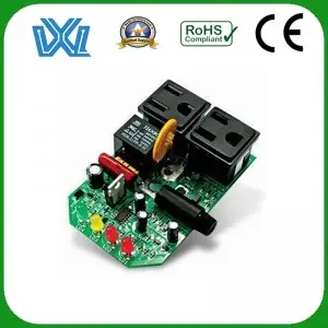
The PCB board is the backbone of any electronic device, the platform on which electrical components are mounted. However, despite their importance, these boards are not immune to failure or defects. That’s why it’s crucial to learn how to effectively test PCB boards with a multimeter. In this blog, we will explore the step-by-step process of testing a PCB board to ensure its optimal function and identify potential problems.
Learn about multimeters:
Before diving into the testing process, it is essential to be familiar with the equipment we will be using – the multimeter. A multimeter is an electronic tool that measures different electrical aspects such as voltage, current, and continuity. It consists of various components including the display, selection dial, ports and probes.
Step 1: Prepare for the test
Start by obtaining a functioning multimeter and familiarizing yourself with its functions and settings. Make sure the PCB board is disconnected from any power source to avoid potential damage or injury. Identify the different points you will be testing on the board and make sure they are accessible.
Step Two: Test Voltage
To test the voltage on the PCB board, please set the multimeter to voltage mode and select the appropriate range according to the expected voltage. Connect the black probe to the common (COM) port and the red probe to the voltage (V) port. Touch the red probe to the positive terminal of the PCB and the black probe to the ground terminal to start testing the voltage. Note the reading and repeat the process for other relevant points on the board.
Step 3: Test Continuity
Continuity testing is essential to ensure that no opens or shorts exist on the PCB. Set the multimeter to continuity mode by turning the selector dial accordingly. Connect the black probe to the COM port and the red probe to the dedicated continuity port on the multimeter. Touch the probes together and be sure to hear a beep to confirm continuity. Then, touch the probe to the desired point on the PCB and listen for the beep. If there is no sound, there is an open circuit, indicating a faulty connection.
Step Four: Test the Resistance
Testing resistors helps identify any anomalies or damage in circuit components on a PCB board. Set the multimeter to resistance mode (the Greek letter omega symbol). Connect the black probe to the COM port and the red probe to the resistor port. Touch the probes together and observe the resistance reading. Then, touch the probes to various points on the board and compare the readings. If the reading deviates significantly or indicates infinite resistance, it indicates a potential problem with the PCB circuit.
Testing a PCB board with a multimeter is a critical step in ensuring its functionality and reliability. By following the step-by-step process outlined in this guide, you can efficiently evaluate voltage, continuity, and resistance on a circuit board. Remember that a multimeter is a multipurpose tool, and understanding its operation is fundamental to accurate testing. Armed with these skills, you can confidently troubleshoot problems and make necessary repairs to ensure optimum performance of your PCB board.
Post time: Sep-06-2023

