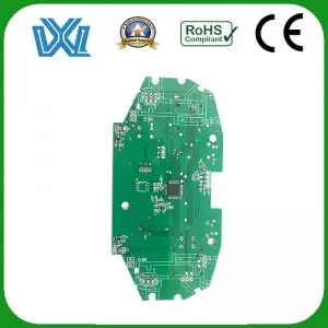
PCB (Printed Circuit Board) is the backbone of every electronic device we use. From smartphones to computers and even home appliances, PCBs are an essential part of the modern world. Designing PCBs requires precision and expertise, and Eagle software is one of the most commonly used tools by engineers and hobbyists for this purpose. In this blog, we will explore the step-by-step process of designing a PCB using Eagle software.
1. Know the basics:
Before delving into the intricacies of PCB design, it is essential to have a basic knowledge. A PCB consists of various interconnected electrical components mounted on an insulating board. These components are connected using conductive paths or traces etched into the surface of the circuit board. Eagle software provides the tools needed to efficiently create and configure these interconnect paths.
2. Create a new PCB project:
Once the Eagle software is installed, open it and create a new project. Give it an appropriate name and set the required parameters such as plate size, material and layer configuration. Before finalizing these settings, keep the dimensions and requirements of your design in mind.
3. Scheme design:
This schematic can be used as a blueprint for PCB layout. Start by creating a new schematic and adding components from Eagle’s extensive library or creating custom components. Connect these components using wires or buses to reflect the desired electrical connections. Make sure your connections are accurate and follow general circuit design principles.
4. PCB layout design:
Once the schematic design is complete, the PCB layout can be created. Switch to the board view and import the connections from the schematic. When laying out components on a circuit board, consider factors such as space constraints, electrical interference, and heat dissipation. Eagle software provides features such as automatic routing or manual routing to create optimized and efficient trace connections.
5. Component placement:
Component placement is critical to the proper functioning of the PCB. Organize the components on the board in a logical and efficient manner. When deciding on a layout, consider factors such as noise reduction, thermal dissipation, and component accessibility. Eagle software provides a variety of tools to aid in component placement, allowing you to rotate, move or mirror components to optimize layout.
6. Traceroute:
Routing between components is a critical stage of PCB design. Eagle software provides a user-friendly interface to create traces between different connections. When routing, make sure they have enough spacing to avoid any potential shorts. Pay attention to the trace thickness as it will affect the current carrying capability. Eagle software provides design rule checking (DRC) to verify your design against industry standards.
7. Power and ground planes:
To ensure proper power distribution and reduce component noise, power and ground planes must be incorporated into your design. Eagle software allows you to easily add power and ground planes to help maintain signal integrity and minimize electromagnetic interference.
8. Design Verification:
Before finalizing a PCB design, it is critical to run design validation checks. Eagle software provides simulation tools to verify the electrical integrity and functionality of your design. Check for errors, make sure connections are correct, and address any design flaws before proceeding.
in conclusion:
Designing PCBs with Eagle software is a rewarding experience for both engineers and hobbyists. By following the step-by-step guidelines outlined in this blog, you can ensure a smooth and successful PCB design process. Remember, practice makes perfect, so keep experimenting, learning and perfecting your skills to create efficient and reliable PCBs with Eagle software.
Post time: Jul-05-2023

